This is an outline of the technique that I developed. It will allow you to make rubber versions of any object that you want (within reason).
This is not a lesson in part or mold design. Im sure other people have covered that in more detail than I can.
This post will go through the process of making a squishy silicone toy Kia Soul.
To get started with this technique you will need:
Things I found to be useful as well:
The first part to any mold project is figuring out what you want to make. Make sure to visualize the object forming and coming out of the mold. Silicone is pretty forgiving so things like draft angles are not a huge concern but they merit some thought. Ask yourself:
I decided that a two part mold with a pour opening in the top fits the needs of this project.
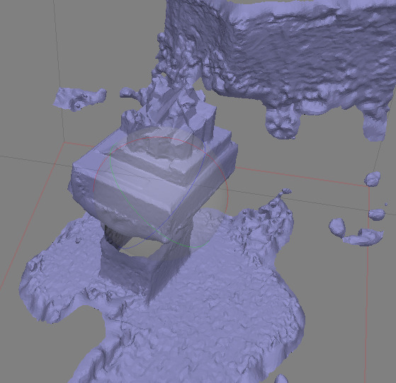
I am going to make this Kia Soul model that I have prepared. Using Blender I remeshed it,
removing and inward facing angles that would make taking it out of the mold more difficult.
For molds, I use my own CAD suite called DSLCAD. The goal is to create a two part mold that I can pour the silicone in from the top.
DSLCAD is a parametric CAD tool that uses a programming language to create models. This is the source code needed to create the mold halves:
|
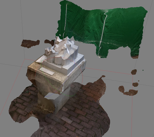
After rendering this model you will get a 3MF file with two mold halves. Any 3D slicer should be able to handle that file and send it to your printer.
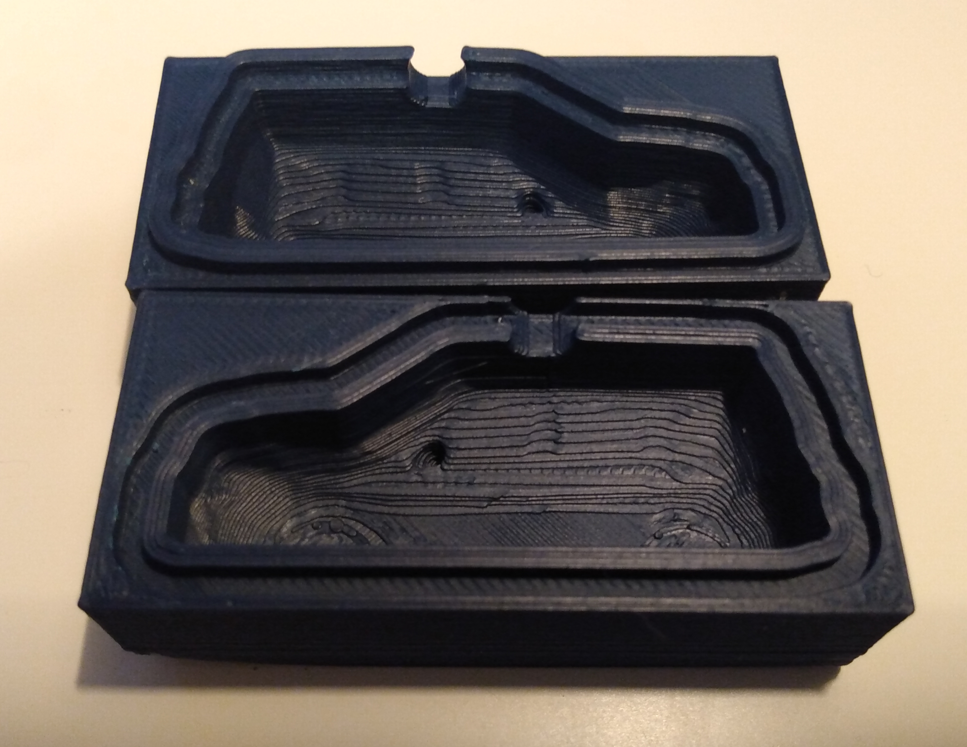
The first half has a groove.
The second half has a tongue that fits into the groove. This helps keep the silicone from leaking out.
As you can see, both sides should be 3D printable. I oriented on their side with the cavity facing upwards to avoid printing overhangs.
There is a bit of overlap near the car tires that could be a problem when releasing the part from the mold. We are using 20A silicone, it bends enough that pulling the part out will be possible. However, if you are using a harder silicone, try to avoid trapped angles like these.
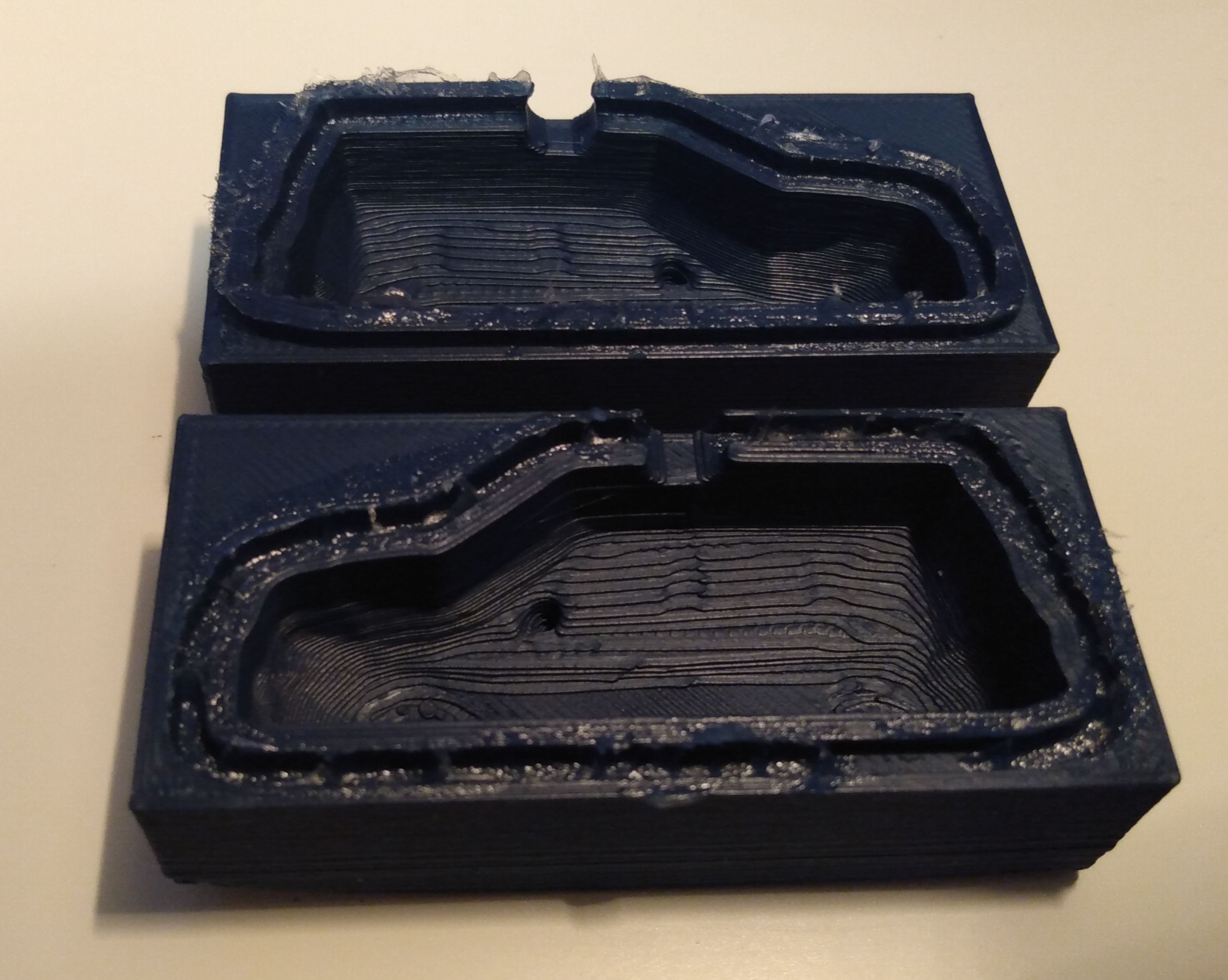
Next we need to prep the mold for casting. 3D printing is not perfect so if we pour silicone directly into the mold it will leak out. The tongue and groove system helps but we need to seal it more. I find vaseline is a great sealant for this. Using a syringe (or whatever you have on hand) put some vaseline into the groove all along one side of the mold.
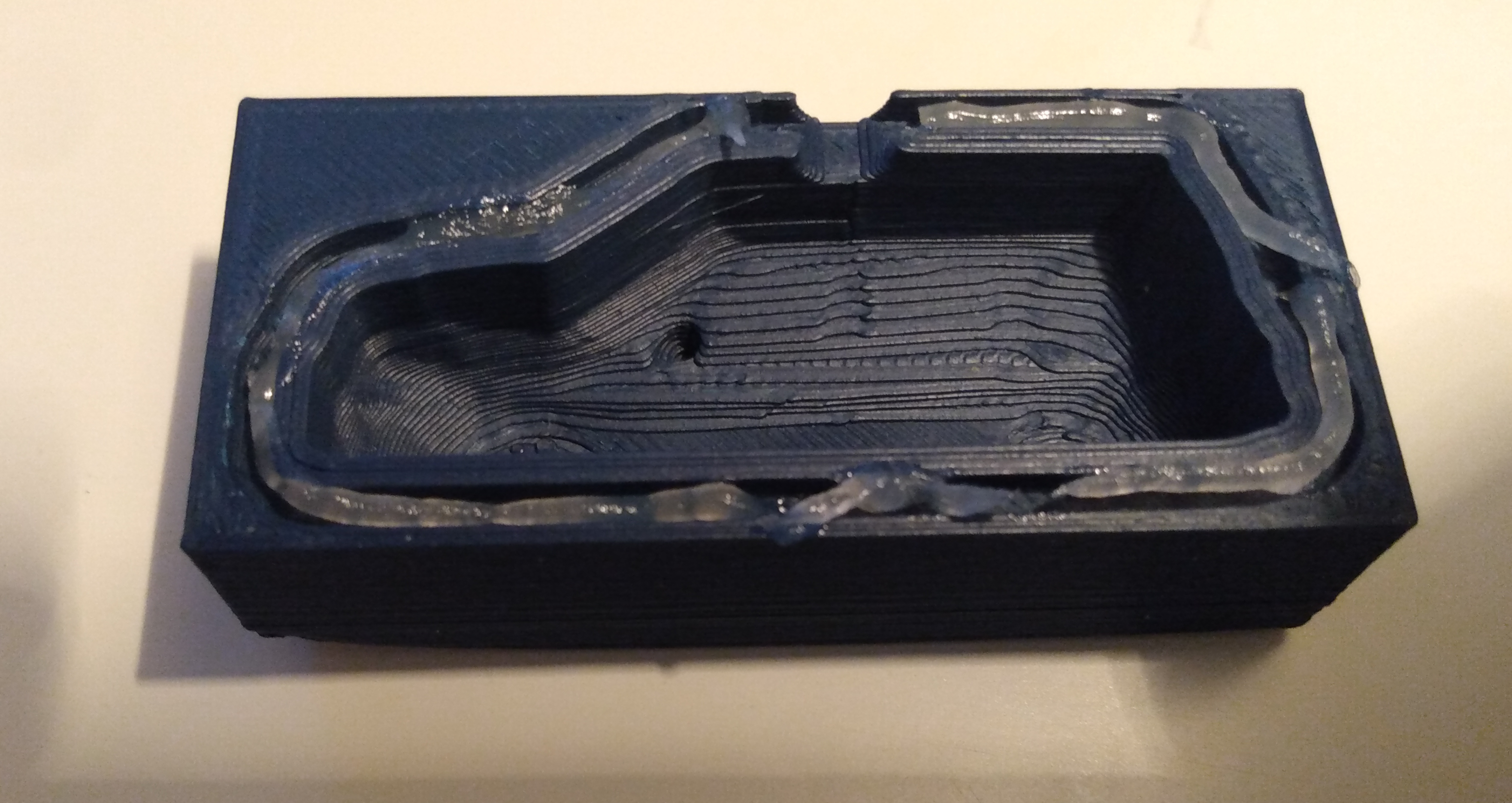
Close the two halves and open them again. Clean off any extra vaseline that may have gone into the inside of the mold. The silicone will flow around any extra vaseline and it will leave defects in the final part.
Close the halves again and secure them together using rubber bands.
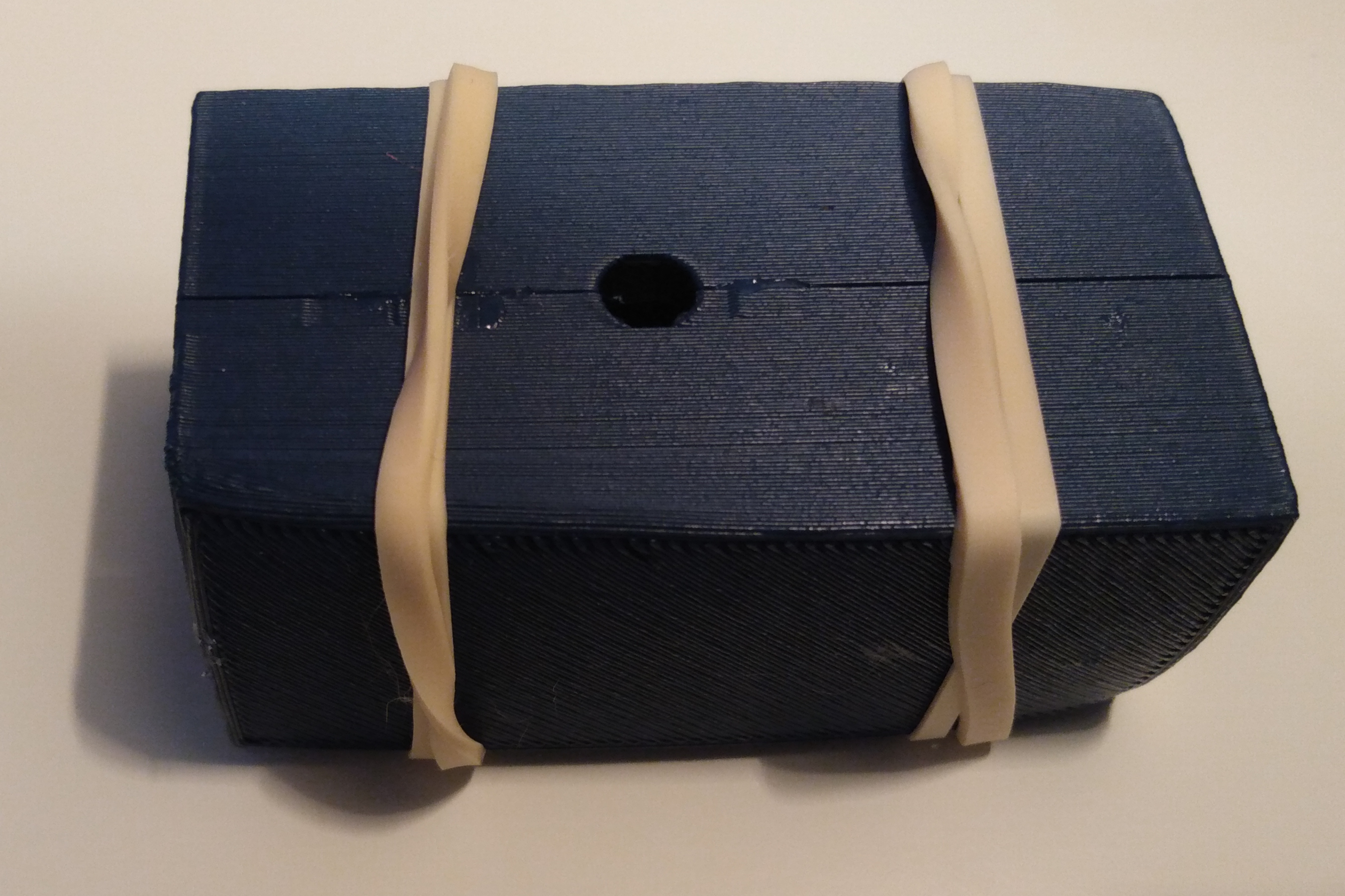
Mix the silicone following the manufacturers instructions. For mine it asks for 1:1 by volume of both parts. I also add a little silicone dye for color. Make sure to mix well before pouring.
Pour the silicone slowly through the hole at the top. Try to get a slow but even pour with a long thin line of silicone flowing from your cup. This line helps keep bubbles out of the final product.
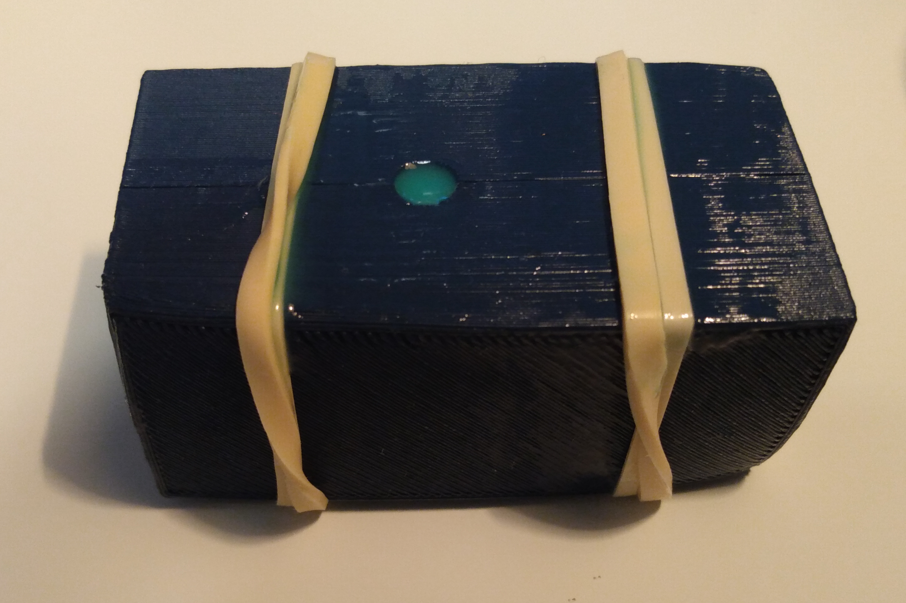
Wait until the silicone has hardened. The silicone I am using asks for 24 hours but I can usually remove the parts after 12 hours.
By this point you should be able to pull the mold halves apart and free the item inside. There will be a little flashing around the seam that you can cut off.
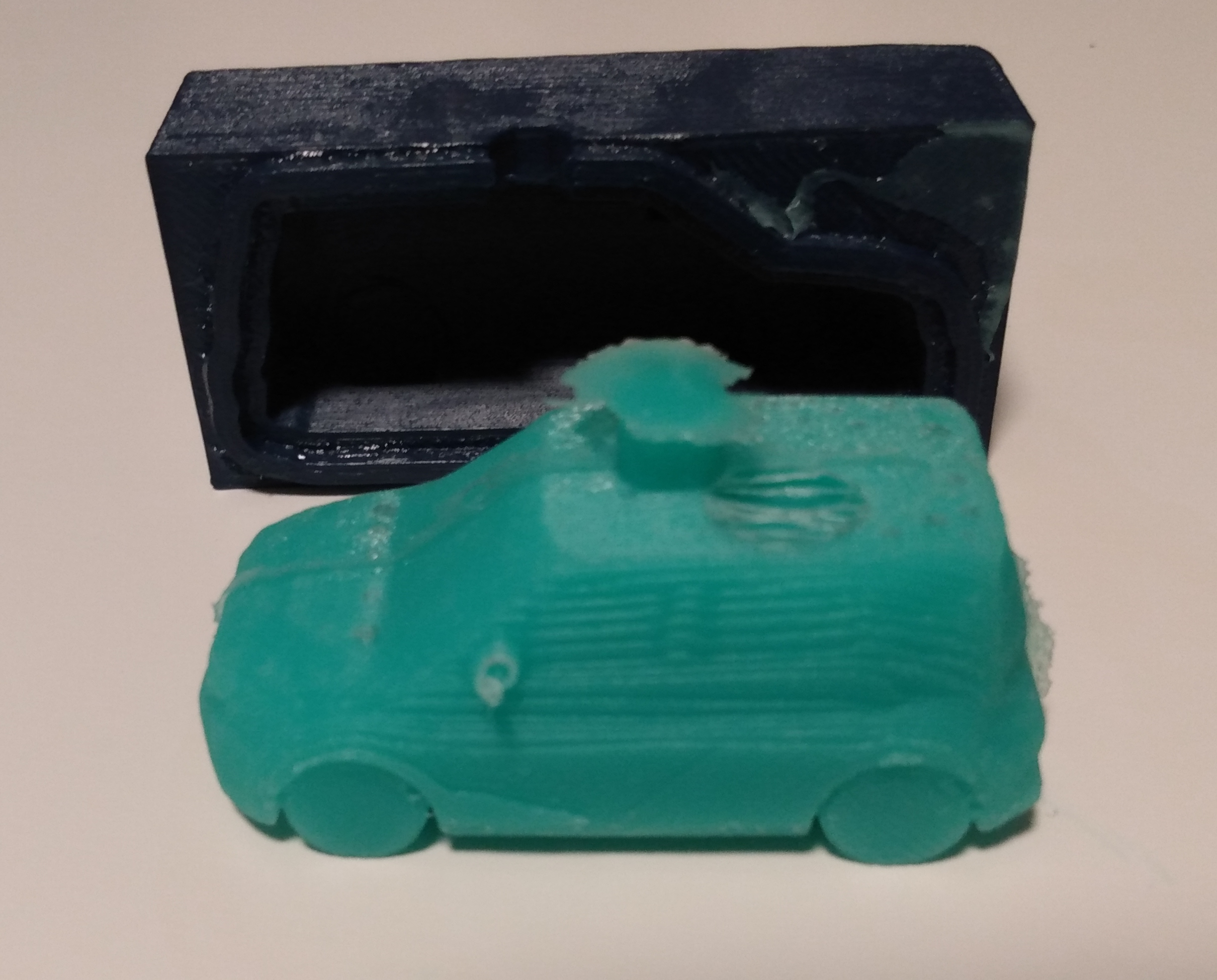
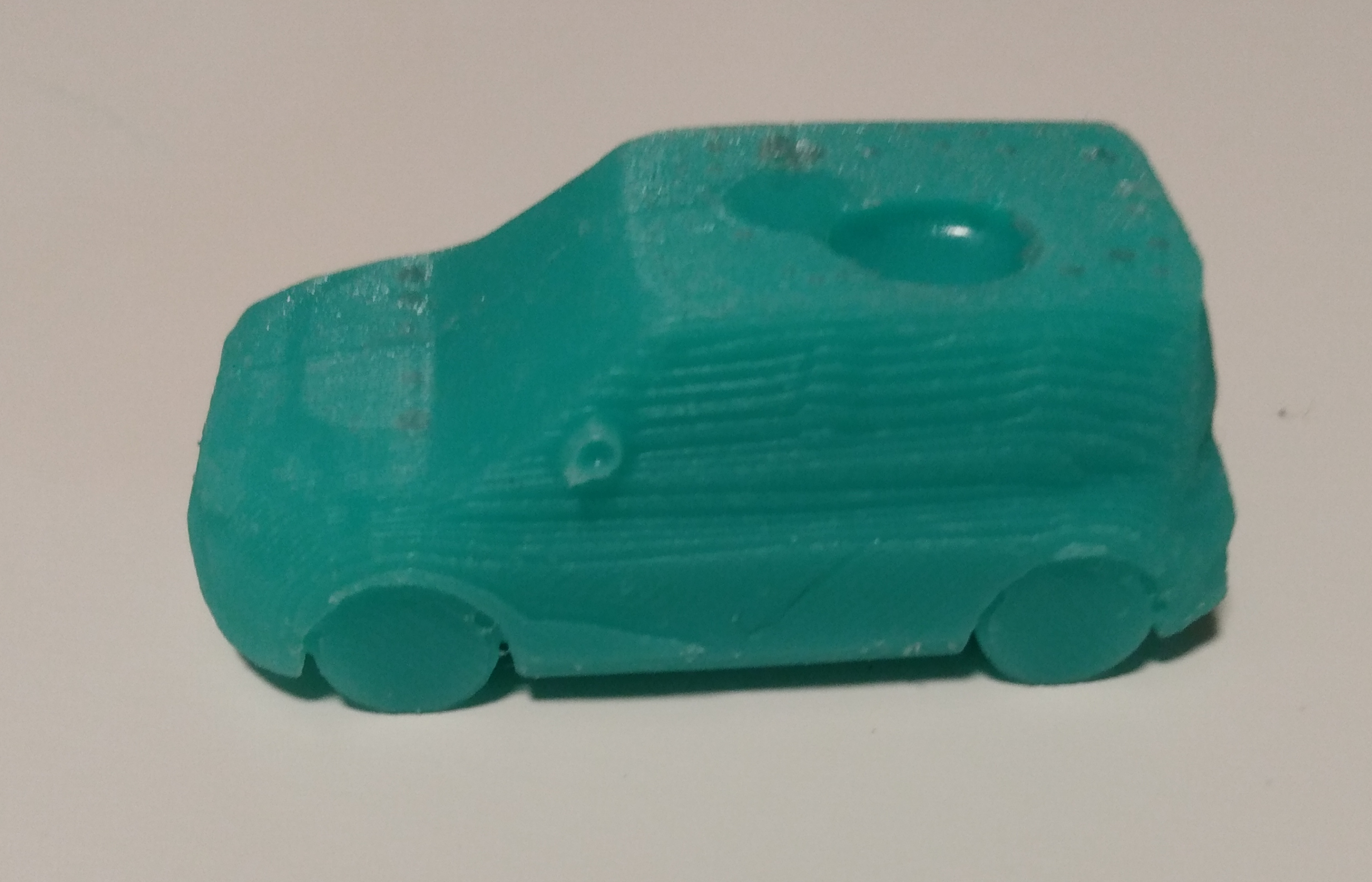
Now you have a new squishy Kia Soul. As you can see there is a large bubble at the top near the pour hole in the mold. This is because I didn’t make the opening large enough and air got trapped. This can be easily adjusted in the CAD model.
I hope that this process was informative. There are a few things that I consider doing to improve in the future:
If you make anything with this method or have suggestions to improve it please reach out and let me know.
]]>These days it has become accepted that many people don’t like their work. Some people want nothing to do with work and they think that the less time you spend working, the better. This is fine and everyone can prioritize what they want in life. It’s okay to feel this way. I think this feeling indicates that you should consider a change but that is a different topic.
I personally enjoy my work. I don’t always like my job. Sometimes there is too much politics and too much bullshit. However, I am a person who likes to create things and express myself through that creation. The creative process, which I am lucky enough to get paid for, is what makes me enjoy my work. When things are good, I get excited to sit and build cool things with my team.
Like everything in life, it’s important to have a healthy balance. My generation is realizing that we can’t work ourselves to death. I have seen people literally become so connected to their work that they became sick and died as a direct result of having to let go of it. Do not let yourself become this attached. If you think that is your case you need to seek help.
There is a danger in being anti-work as well. For someone who enjoys work, it’s possible that other people might not understand why. That misunderstanding leads to conflict. If you want to work and people tell you that it’s wrong, there becomes a disconnect. Finding joy in something and then being told that you shouldn’t causes conflict. It reduces the joy and makes you fight that conflict every day.
We all want to enjoy our life. Don’t work too much; don’t work too little. Let yourself concentrate your energy fully into the work you do. Be happy with your time at work the same way you are happy with your time at home.
]]>The problem is that this is big. It’s a chain that started many years ago. Even if we fix it now we won’t see changes until many years in the future. And the key word here is we, not I. Climate change is a global issue. That scares me.
I do my best. I don’t buy many things. When my stuff breaks, I repair as much as I can. When I can’t repair, I recycle. I don’t even drive very much, less than 15000km per year. From what I can tell I do most things that people recommend.
Still its getting warmer. Still its getting wetter. The cold winters of Canada are gone, I will have my memories and that is all. I fear that in another 20 years, I won’t recognize the winter anymore. For this I am sad.
To quote a great book: “fear is the mind killer”. This is a state of panic that doesn’t help anything. I am in a state of panic that won’t help. This fear won’t bring back my winters. This fear won’t save the future. Action will do that.
I am writing this to call out to all of you. Everyone who feels the same fear that I have. I want you to know that it is ok. Do the best that you can do. We don’t know where we are going, but I promise I will be there with you, and we will figure it out.
]]>Start a new project like you would start any project. Dream big and find a need that will help you and help others. The next steps will force you to question this dream so make sure you believe in it from the start. If you cant make it through the next steps come back here and work to find a project that will endure.
Now pick an aggressive timeline. How much time do you realistically have to work on this new endeavour? For me a realistic timeline is often an afternoon or if I am lucky a weekend. At this point you should be asking yourself “How can I possibly solve this big problem in so little time?”. You will want to extend the timeline into multiple days or weeks. Fight against this urge and limit yourself as much as possible.
Now you have to make everything fit together. Go for a walk and let your creative brain work. You have a big problem and a really small amount of time. Your job is to work within this boundary. You are not allowed to change the timeline. Figure out how to shrink your problem, distill it down to its most core essence. Throw out everything that can be removed. This is the time to be ruthless and aggressive with your ideas. Find out what you actually need in order to complete your project.
By this point your idea should be really really small. You should have one if not two interesting problems to solve before the idea will be completed. Extra parts like fancy UIs, online accounts and project management features should be long gone. What you have now is a small project. It has a clear start and end. You should be confident that it fits within your timeline. Now is the time to bring your project to completion. If you followed this process, you should quickly go from nothing to a completed project in a matter of hours. You will be proud of the results.
The key is to be realistic. Companies pay millions of dollars to build complex apps and to convince you that you need to build the same complexity into your own projects. That is unrealistic. Make your projects small and finish them every time.
]]>In this post I will be going through an example of how to build a configurator where anyone can customize the 3D models that you design.
The first thing you need is a SCAD model. For example here is one with a few variables. It generates a 3D gear using four variables to control the pitch (density of teeth), number of teeth, thickness of the gear and size of the center bore hole. I am using the MCAD library to generate everything.
|
If you wanted a gear with 100 teeth, running the following command line code on your computer would generate a STL file containing such a gear.
|
This process of setting variables in the model is the exact same approach that the configurator on this site will use.
Now we need to make things more user friendly. Command line is great for programmers but is scary for most people. Instead lets use some web development skills and build a form using HTML.
This is the same kind of form as you have seen all over the internet, there is one input
for each of the variables in our SCAD file. All of the inputs have default values. At the bottom of the form there is a button that the user can click when they are finished customizing the gear.
|
Hook this form up in any website and it will look seamless. The user wont even know that they are editing OpenSCAD models unless you tell them.
Now comes the hard part. We need a way to run OpenSCAD when the user clicks the generate button. We could run it in the page but that would freeze the browser while the model generates. Having a frozen browser sucks. Luckily there is a tool in browsers called web workers that we can use to avoid the freezing.
Web workers are like background tasks for websites. By running our code in a worker, it can take as much time as it wants while the site stays fast and the user can keep browsing.
Here lets make a file called openscad.worker.js
. The worker code waits for a message to be sent to it from the webpage, then it will run the exact same command line we used as the example above. When it is finished generating the 3D file, it will pass the data back to the webpage.
|
Next, put the worker code in a folder next to all the files downloaded from the releases page at DSchroer/openscad-wasm. Currently workers don’t support ES6 imports like we used on the first line. Use a bundler like Rollup or Webpack to combine all the imports. This will make sure that the worker will load safely.
Finally we need to tell the webpage how to talk to the worker. Add the code below to your page. It will create the worker and send it a message with all the variables from our UI. Then when we get results back from the worker we download them as a file to the users computer.
|
Put all three pieces (the model, the UI and the worker) together into a website, add some CSS to make it look pretty, and publish it for the world to see. With these tools and a little bit of work, anyone can share their own 3D projects and let others customize them. You can even build more complex things such as 3D viewers and full CAD editors. My hope is that now that OpenSCAD can run in the browser it will convince more people to use it and help drive more CAD as Code projects.
Here is my example gear configurator:
If you want to make your own configurator, feel free to fork this project on GitHub as a base: DSchroer/openscad-gear-configurator. Also give it a star so I know you came from this post.
]]>In this post I want to walk through my process of building the lower head tube lug using OpenSCAD. I do assume that you have an understanding of OpenSCAD, this is more of a guide than a beginner tutorial.
Here is the final result. I will walk through how it came to be. There is a cup at the bottom to hold bearings, two pipes that join at a given angle and some nice rounded fillets to make the part look nice.
The first thing to go over is the project setup.
|
I import/use a few different scad files. utils
holds a few helper methods that help make the modeling process easier. The ones I use are the span
and arrange
modules that make it easy to align things to vectors using linear algebra. Span takes an object, rotates it to the vector and scales it to the vectors length. Arrange takes an object and only rotates it along the vector. tubes_variables
holds all of the bike frame geometry that I use later on.
In order to make this process easier I have written a few more helper modules. to_frame_coords
takes a model that is in global coordinates and puts it into the correct position on the bike frame. to_lug_coords
does the opposite, it takes a piece of the bike and moves it to global coordinates.
|
A note for those reading the code. My naming convention for variables is that constants are all uppercase (LIKE_THIS
). Three dimensional vectors start with a v_
(v_like_this
). Any modules or functions are simply lower snake case (like_this
).
The first thing to build is the cup that will hold the bearing at the bottom of the head tube. The process for building parts like this is to start with a 2D version of it and then stretching it out into 3D in some way.
|
The cup is first modelled as a cross section that will be extruded in a circle to make a cylinder. Using the polyRound
module from Round-Everything and setting up points, the section ends up looking like this. You see it does not look like a bearing holder yet but if you picture cutting a thin slice out of a bagel, this is kind of the same process in reverse.
By applying rotate_extrude
the cross section is turned into a cylinder by rotating it around an axis. The slice fills out and creates the rest of the bagel. Creating the final bearing cup as seen below.
Now moving on to the top of the lug. This is purely for looks and will give the ends of the lug some nice smooth edges rather than sharp 90 degree ones. This follows exactly the same 2D to 3D procedure.
|
Start with the outline of a cross section. This time its just a rectangle with a single rounded corner.
Then rotate_extrude
to produce the shape. Note how the rounded corner ends up flowing around the entire edge.
Finally we get to the interesting part, the join between both tubes. Unlike the first two sections this one is hard to build using the 2D to 3D method from before, so we are going to start directly in 3D.
|
Start by setting up the intersection. Create both tubes using cylinders. Move the two cylinder to the same location and angles of the tubes so that they join up where the tubes are connected. This creates the basic form but looks quite sharp where the two cylinders are connecting.
To smooth out the connection we are going to use a new tool. With the unionRoundMask
tool of Round-Everything we can specify a cube as the rounding mask and have it create a nice fillet around the join. The mask lets us specify a 3D area where rounding should occur and then the tool will round all of the edges between the cylinders within that area.
Next we need to put all of our parts together into a single solid block. This will be the final 3D outline of our lug but without the holes inside for the tubes to slide into.
|
Using the helpers from the start, we move all of the modules into their correct position in global coordinates. This creates the final solid part. Now its starting to look like the lug that we are building.
Then finally we need to cut the space that each tube will slide into. Using some more helpers we move it on top of the frame and use the difference
module to hollow out the part where the tubes will go. This cuts out everything where the lug and frame overlap and leaves perfectly sized holes within the final part.
|
Now after rendering everything the head tube lug is finished.
This pretty much covers my process for making parts. As much as possible start with a 2D cutout of what you are building. Afterwards, extrude the cutout into a 3D object. Then apply various modifiers to the 3D object until it is the size that you are looking for.
I want to say a huge thank you to the Round-Everything library creators and maintainers because without them this piece would probably look a lot different. If you are trying to create nice looking functional parts in OpenSCAD I highly recommend using this library.
]]>I have a lot of AVR microcontrollers. They are small 8-bit chips that are good for controlling small circuits. If you have ever used an Arduino the AVR chip is the main chip inside it. My goal for this week is to have my compiler produce a hex file that I can upload and run directly on one of these chips. More specifically I want to run it on an ATmega328P.
For starters I am going to write some C. There are a lot of little details in the AVR platform that I don’t really want to worry about in my backend. To clear things up, I made a runtime that my program can link to. Having a runtime lets me have complex logic that is best expressed in C or even assembly but still use my own generated code for the final results.
|
The runtime is simple. It sets the clock speed used by _delay_ms
, it has a setup
function that makes DDRC an output, has a portc
function that sets the value in PORTC and has a delay
that waits a given number of milliseconds. This is enough to make a simple blinking light program to validate that everything is working.
Now I need to build that runtime into an object file that I can include with the compiler and link with later.
|
Now that the runtime is ready we need to generate some code that will use the runtime. This will make use of our runtime and generate a program that blinks an LED every 100ms.
|
You can see it has a setup area, then an infinite loop that turns the light on and off with delays between. Its a simple program but baby steps are important.
Where things start to change since last week is the target machine setup. Instead of initializing x86, I am initializing all. This is because the rust bindings that I use do not have AVR APIs exposed even though I have them installed. By running all, I know that the AVR target will be initialized. Then for the machine we use avr
and atmega328
to target the correct chip.
|
Same as before linking runs the avr-ld
command under the hood. This time I used avr-gcc -v
to determine what linker flags are needed in order to produce a proper binary.
|
This should work but there is another piece missing. The program that is produced after linking is an ELF binary. Those are mainly used by unix like operating systems. Our AVR chip does not know how to read ELF and instead we need to transform it into a Intel Hex file. We do that by making some more temporary files and running avr-objcopy
to extract the program as hex.
|
Finally we put it all together in our entrypoint. When you run the program it will generate a file called blink.hex
that you can flash directly to a ATmega328 microcontroller.
|
To test all of this I got out a breadboard and wired up a microcontroller and attached a LED to the correct pins. You could also use an emulator if you prefer. As you can see below, the program works and our microcontroller is operating the light.
]]>I chose to work with LLVM because it has some great properties. I wanted a tool that could create native binaries. In my opinion, there is a huge advantage of having native code over using an interpreter or vm. I also know that LLVM has a well supported and known API. It’s a great way to get started building compilers that you know will work because other people have done it.
This week, my project will use LLVM to produce hello world
binaries. There wont be much flexibility but it will show the basics needed to setup your own LLVM compiler.
I set out on this project with the following goals:
In summary, running it should be the only step to produce a runnable binary. I refuse to run the results of my compiler through clang
. I will allow using binutils
because thats what other compilers do, so calling ld
is fine.
I started by looking at LLVM bindings for rust. The two big options were llvm-sys
and inkwell
. I chose to use inkwell
because it’s a simple wrapper around llvm-sys
that makes things slightly easier to use. I might have to use llvm-sys
directly for future projects depending on how much tweaking to LLVM I end up doing.
The first goal is getting it to produce LLVM IR that will print hello world. I built this function that borrows the LLVM Context and builds up a function called main
.
|
The main
function goes ahead and passes a reference to the string "hello world!"
to a call to puts
. That will print the text to the screen. That is the minimum that we need for a program. Now the real challenge is turning that LLVM module into a working binary.
The next stage is to create a target machine that can compile that IR into an object file. This is where LLVM will do its optimization passes as well.
|
Finally to pull it all together, we need a way to link this object file with other libraries. Since our code uses main
and puts
we will need to link libc
. Finding the flags needed to do this was not straightforward but there is a trick that I discovered.
Let’s say that we have an assembly file called a.s
that contains roughly the same code that we are generating. Run clang -v a.s
, using the -v
flag tells clang to run in verbose mode. That will print out all of the arguments that it passes to ld
under the hood. Using that technique, I was able to build out the following linker tool:
|
You can see that there are a lot of additional flags that we need to pass to ld
. The process works as follows:
libc
Once we have that working we can put it all together:
|
Here we create the LLVM context and use that to create our application module. Then we build up the target machine and use it to compile our module into a x86_64 object file. After creating the object file we need to link it using ld
to produce a runnable binary. Finally we take that binary and write it to a file called a.out
that the user can run. In the end the results look like this:
|
All of that work to create a hello world
binary! Now we have all the pieces in place to build full compilers. They can parse complex grammars and produce native binaries. In the coming weeks we can use these building blocks to create anything we want.
The program for this week is a logic language. You can give it facts
or ask it queries
. Facts take the form of SOMEONE is FACT
and queries take the form of who is QUERY?
. The program keeps track of all the facts and performs the desired set operations to find the result. You can use and
, or
and not
as well as ()
to build up complex queries.
The lexer is very simple. Using logos again we come up with a few tokens but nothing unexpected here:
|
The parser is much different than my previous attempts.
First off the AST is split into multiple enums rather than just a single one. I found this to be a cleaner way of representing the different levels of the program. At the top we have Statement
. A statement actually does something within the program. It changes state by either setting a fact or printing the results of a query. Below that we have Expression
. Expressions are used to build up queries and can be nested to build something more complex.
The parser itself takes the lexer and starts reading tokens. It is a recursive decent parser. That means that it starts at the top and looks at the next token that comes in. If its a Token::Who
then it calls the query
parser and goes down that path. If its a Token::Identifier
it call the fact
parser and goes down that path. Each path is very similar to the parser combinators we build before but rather than having a data structure that puts the parsers together, we are just using normal function calls.
One thing I would also like to point out is that I discovered the ?
operator in Rust. It makes it super easy to use Result
and Option
in your code. Rather than having to use unwrap
or is_ok
you can just add a ?
and if there was an error rust will return that error.
|
The final parser is about the same size as before. However, error handling is a lot better and its easy to debug and step through what is happening. Overall I am happy with this approach and will probably continue using it.
The runtime for this program is kind of simple but interesting none the less. It keeps a HashMap
of all the facts it knows. So if you tell it rust is cool
then it stores cool -> ["rust"]
. Then if you query it with something like who is cool?
, its just a quick lookup into the table. More complex queries take the form of set operations. Union, intersect and inverse are used to create and
, or
and not
.
|
Finally the REPL is very simple as well. It reads the input line by line, if there is an error then it prints it, if not it runs the parsed statement in the engine and prints any results.
|
Here is some output of running the program:
|
After this week I am pretty happy with the technology stack that I am using for the compiler frontends now. Logos plus a hand built parser seems to be ideal for me. So next week I will probably look into writing some compiler backends and see if I can get some native code compilation working using LLVM.
]]>pebble_parser
. Its a similar parser combinator library to pom
but with a better syntax and it works on iterators rather than arrays.My project for this week was to build a BrainF**k compiler. Its a simple language with very little syntax. I figured it would be a great way to test out my parser without having too hard a project to complete.
There are not many differences between this post and my last. I am going to quickly point out the parts of interest and leave the rest as an exercise for the reader.
The lexer is very similar to last time. Using logos
and mainly focusing on basic tokens.
|
In a similar sense the runtime is simple and similar to the last one as well. It is recursive and holds some common references. The big difference is the looping structure and block evaluation. As you can see here we use existing structures within rust to simply execute as needed.
|
Finally there is the parser. Here is where I began to work with full intentions of ending up with a cleaner parser that contained better error handling. Unfortunately, what I ended up with was more or less the same as last time. I like the method calls more than operator overloading, but the parser is the same speed, has bad error handling, and is generally the same thing in a different syntax.
|
Like the last project this one works fine. It will run any BrainF*** program that you want. However the implementation is not an improvement over last week.
Parser libraries like pom
and pebble_parser
are not the correct approach for any big compiler work. The source code of the compiler is much better at handling complex worflows than libraries. For that reason I wont be releasing pebble_parser
as I don’t think that its the correct solution. I’m now thinking that using logos
is enough to build a toolchain. My next parser will be hand built and I will see if that works out better.
My goal of this week was to figure out what tools to use when building compilers in rust. I needed a good lexer and parser. Ideally a set of libraries that are easy to use, expressive, extendable and with good error messages.
To test this I build a very simple calculator REPL. It takes math input like this: 5 + 5 / 10
and will print out the answer. It will not handle brackets, order of operations or any other intricacies of calculators. Those are problems for a later time.
The first thing to build for the compiler is a language definition. I roughly used the following definition, written here in BNF:
|
I should have started by figuring this out before writing the rest of the program, but in this case I wrote it afterwards.
You can see that a value is a valid equation. A value is basic decimal notation with an optional minus sign: -10
, 5.6
, -0.01
and so on. The simplest possible program is the text 0
. Then you can combine values with a series of symbols 5 + 5
, 100 - 60
or 1.5 + 1 - 1.5
.
There is one ambiguous part of this definition. The -
symbol can either be used to create a subtract expression or a characteristic with a minus sign. This could be improved for a future version. For now the program will just need to separate operator and the value with a space.
The lexer is responsible for taking a stream of text and converting that text into a stream symbols that are easier to work with. This is the first piece of code that rune. For example the symbols '-', '1', '0'
would pass through the lexer and become Number(-10)
.
For this I tried using Logos. The reason that I chose it was that it was easy to implement. Did not require many traits to be implemented and allowed for simple regex based parsing. The final lexer is here:
|
The logos library did a great job of making lexing simple. Adding a few macros to an enum was all that is needed. You can even reference functions within the macro to add extra functionality if the built in conversions are not enough (number
is an example of this). Unfortunately I had to implement some extra traits for the parser in the next section. Those traits made the parser more complex than it needed to be.
I think the thing that I would do differently next time would be to return the Lexer
type directly rather than converting everything directly to Vec<Token>
. The Lexer
type has methods such as span
and slice
that would be super useful when generating error messages later.
The parser takes the stream of symbols generated by the lexer and converts them into an AST. The AST is much more useful because it contains information about how the program is structured rather than just being a big list. For example Number(1), Plus(), Number (1)
becomes Equation(Value(1), Add, Value(1))
. With the AST the program should have the same understanding of the input as the programmer who wrote it.
For this I went with pom. It is a fairly simple example of a parser combinator library. The main thing that drew me here was that there were no macros and everything could be adjusted.
|
At the moment I am not fully satisfied with pom. The library seems to have been built with the goal of parsing text rather than symbols. From what I saw there was no way to extend the error messages and reference different spans that came from logos. I would also prefer not to use overloaded operators for the combining stages. I get that its clean when you understand all of the symbols but their implementation is not intuitive. Functions with good names and comments would be better. Ill probably replace this library in future versions.
The core of the program was very simple. One module that runs all of the math calculations. It simply looks at the AST and converts it into simple commands to run. It recurses down the tree and executes what it can. Eventually it will return a number that can be displayed.
|
The main program just puts all of the pieces together. There is a loop that grabs input. That input goes to the lexer to be converted into symbols. The symbols go to the parser to become equations. The finally the math engine runs the equations and prints out the results. Those steps repeat until the program is closed.
|
Overall, I think that this was a good first start. I really liked working with the logos library. I think it did a great job of building a lexer and made it easy to understand what I needed. The pom library was a good start but I will probably look for something better later. It just does not align with my mental model of how the AST should work. Maybe I just need to build a wrapper around it or something.
Next time I want to dive deeper into the parsing side of things, so it will be a good time to experiment there.
]]>This is common in the world of online files. So I started to wonder: How can we build software that does not continuously confuse people?
Context matters. If you open a folder on your computer, it is different than opening it in a web browser interface and it is different than opening it on your phone. In computers a lot depends on context. Files are a great example of this. They are a building block of modern computing and there are many different contexts where people work with files.
The file browser view is iconic to our industry. Anyone who has used a computer with a GUI (Graphical User Interface) knows what a file browser looks like. It looks the same as it did in classic Windows, with a list of files in the centre and often some common folders on the left. Any place that you find files, you will eventually encounter a file browser that looks familiar.
While they look the same, they do not act the same. Some file browsers can create, edit and save files. Some can only show them. Some can only work with certain types of files. Some wont even show the correct list. This is often a platform limitation. To do something with a file. users need to move the files from one file browser to a different one. To a user this is confusing.
Is it a bad thing that we have so many different browsers? Are there ways to simplify and streamline this fragmented system? I think its important to look at these questions since every new file browser and every new context makes it harder for people to know how it all should work. It silos our users and keeps them within a smaller ecosystem.
]]>In order to follow along, you will have to have the following setup: Docker, Google Cloud Platform and Terraform. This is not a tutorial for any of those technologies. I assume that you already have some experience working them. If you would like me to write a tutorial in a future post please email me and let me know.
The first thing that we will need to setup is our docker image. This will contain the server and any customizations like mods and settings that you may want to use. I chose docker since its the industry standard for setting up applications for the cloud. It also lets me customize the server easily without having to worry about the cloud configuration.
First thing to do is prepare the required files:
Download the forge server installer from the project website. This will be the application that runs the server and loads our mods. It will automatically install the Minecraft server and configure it for us.
Create a file called server.properties
and fill all the properties that you want to use. A complete list of the default properties can be found on the Minecraft Wiki. Make sure to customize the settings to your liking.
Finally create a Dockerfile
with the following contents:
|
You should now have three files:
If you want to add mods support. Uncomment the line within the dockerfile and put all the mod jar files in a folder called mods
.
Build the docker image by running the following command:
|
After building push the image to a public repository of some kind. In my case I used us.gcr.io/personal-147022/minecraft:1
since it is part of my google cloud project.
Now that the image is completed, it needs to be run somewhere. For this project I chose to use Google Cloud Platform because it was cheap and I already have experience working with it. The deployment needs two things to be setup:
I decided that the setup should focus on cost savings and be optimized for periodic gameplay. The idea being that my friends and I only game once a week so the server should be shutoff for the rest of the time. This will keep costs very low. I decided to use preemptible machines because they are cheaper. There is a risk that the server may be shut down during the time that we are playing however it should be simple enough to restart it.
In order to keep the setup very simple, I have written a terraform module that you can find at my Github/GCPMinecraft repo. This module takes care of the setup and configuration within GCP. It will only work with Docker based image servers like the one described in this tutorial.
Create a terraform file as follows that adds GCP and the correct settings within the gcp-minecraft
module:
|
The gcp-minecraft
module can be customized in a few ways:
Running terraform apply
on this file sets up the new VM and creates DNS configurations for us to use.
Finally I need to take my website schroer.ca
and link it to the newly created cloud DNS records within Google Cloud. The reason I did this is to make sure that my friends have an easy to remember URL for the server and if I want to make changes I can do so without them being affected. Using the mine
subdomain I setup the following DNS records that give Google Cloud control over that subdomain.
|
After this change is added it may take up to 30 minutes for the DNS records to update. Be patient.
I hope that you found this guide helpful. There is lots to explore and play around with once the basics are setup. Customize and experiment with different setups. I would like to hear about what kind of modifications you make.
]]>Powerline adapters work by plugging the devices into two locations on the same electrical system. They send high frequency signals across the system that can be read back out on the other side. Just like an ethernet cable, these adapters are physically connected using the wiring that is already in your home. However there is a catch, the line is shared. This makes the adapters sensitive to interference caused by other equipment. In this article I will cover how to diagnose connection issues and how to optimize your powerline network. I am using the D-Link DHP-701AV for my power adapters. Some of what I have learned will work on most adapters but there is some information that is specific to these devices.
One of the things that I don’t like about the powerline adapters is that they “just work”. The idea of “just work” can often be a replacement for good configuration tools. The goal is to ensure that all points in my network can take full advantage of this connection and will not slow down down from the adapters. In my case I have a 50Mbps DSL internet connection. Unfortunately my adapters were only transmitting ~4Mbps even though all the connection indicators were green. After contacting D-Link support for more information on troubleshooting the connection I was told that it should “just work” and there was not much that could be done. They also claim that there is no way to connect to the device to get more information. Both of these claims are wrong.
The first thing that you need in order to improve a network is to understand where the bottlenecks are. The connection between powerline adapters are mainly affected by two things: distance and interference. Distance is not how far apart the two outlets are, in reality the distance is based on the amount of electrical cable that connects the two outlets. This means that how far apart two devices are will not be a good indicator of the connection. Regarding interference, a lot of online resources claim that large appliances such as fans and washing machines cause interference that affect powerline adapters. Contrary to those claims, in my research I found that it is much more likely that small electronics with cheap switching power supplies will cause the majority of interference. Minimizing electrical cable distance and removing noise should be the main goal of any powerline network.
It is important to find out exactly how strong the connection is between each device. As I mentioned previously, all of the indicators on my adapters are green. The range of acceptable speeds for a green light seems to be any speed that holds a connection. Thankfully there is a tool provided by D-Link that allows a laptop to connect and configure these devices over the network. This gives a much more accurate view compared to the red and green indicator lights on the device.
Download the D-Link PLC Utility for Windows . This utility allows you to:
To use this software simply install it onto a laptop. Plug the laptop directly into one of the powerline adapters that is connected to the wall using an ethernet cable. Hitting refresh in the software shows all of the powerline adapters within your network. The lines connecting each adapter shows the connection speed between them. With this data the rest of the network can be accurately configured.
To map the network I plugged one device into the wall near my router. I took a floorplan of my apartment and labeled the location of that device “Entry”. After setting up the fixed device I took the other adapter and plugged it into every outlet that I could find and recorded the connection strength between each point. Initially I assumed that the connection strength would drop linearly as I got further away from the device. This was not the case and as you can see from the diagram below, some outlets perform much better than others.
Now that there is a baseline, some of the connections can be improved. As seen above the connection strength seems to change randomly from plug to plug. It is important to find patterns because this will give insight into how the electrical systems are organized. With this it is possible to determine the best locations to place each adapter. In order to get better insight into these patterns, I picked the outlet that would likely generate the worst possible connection and re-ran the same tests. The results are marked on the diagram below.
After testing my worst case, there are some strange results. It appears that the lower right side of the house is connected by a single electrical line. This line spans both stories and makes a strong connection between the office and living room. These connected lines will likely be helpful in determining the ultimate final configuration.
Since the worst case test showed some unknown connections, the next test was my idea of the best case. It turns out that the side outlets were not on a very good connection. These outlets are less well suited to host a connection. Identifying dead zones can be just as useful as finding good connections.
In the end my final layout ended up using the same entry point that I started with. For the outputs I chose to use the best outlets that I had discovered over my tests. Unfortunately none of the connections are as fast as I would have hoped but all of the connections are at least reliable. My goal was only to have a faster connection than my base internet speed, so all of these values are acceptable.
Interference from other electrical devices also has a large effect on powerline adapters. It will drastically reduce the final speed even if adapters are located on good lines. Detecting this interference is difficult however there is some information that can help:
It is a good idea to establish a baseline by unplugging as many devices as possible and then re-connecting them one by one to identify any that may be create too much electrical noise. In this case look for things like small electronics, laptops or other devices that would have a compact power supply. On my line I discovered that my laptop along with a small electric drink warmer was causing the most interference. If you have a connection and you don’t know what side has interference, run a speed test and compare upload and download speeds. If the download speed is bad but the upload speed is good then the interference is at your current end of the line.
To remove interference you can move the device to an outlet that is further away from the powerline adapter. If this is not an option there are also powerline filters that you can purchase online such as this Insteon Powerline Noise Filter.
]]>The morning of the run was a chilly -10 degrees with a light dusting of snow coming down. A group of around 20 people turned out for the run. There was no particular demographic, just a bunch of running enthusiasts. Just a group of young and older runners shivering out in the snow. So as is normal when the race started, I put on my headphones and began to go at my own pace. I was feeling confident that the 10k would be easy and, for the most part it was. The light snow had covered the trail a little, there was also occasionally a small amount of ice. None of that worried me because I was well in the zone by this point. My running playlist was been perfect and with the clean air I felt exceptional. Just as I reached the 7k turn around point, while thoughts of a good finish were firmly in my mind, I put my foot down onto a bit of black ice without noticing. My feet slid out from under me. I panicked and threw my hands down to catch my fall. Hitting the ground hard in two places, I could feel the shock as I realized what happened. First my knee scraped across the cold ground, ripping my pants and my skin. Then down came my hand. It hit square on, it hurt and was stiff, but there was no sense that anything was really wrong. After that I did what came naturally, I got up and kept running. After all, it was just a small fall right?
By the end of the morning, I was pretty convinced that I had sprained my hand. I had sprained things before, so I knew it would swell, it would be sore and it wouldn’t move easily. I don’t know if I played it off too well or everyone else had the same idea. We just went about the day and I put my hand on ice. It had swelled up as expected but the pain started to get better. When it did hurt, I assumed it was normal and that I could just tough it out. After all it was just a bruise, it would get better. Looking back now its easy to see what I did wrong, but I didn’t have the experience that I have now. So I kept acting normally, I used my hand a little and iced it a lot. The swelling went down and I figured that I would get better quickly. Before I knew it my trip home was done, and I was on my way back home to Montreal.
At first, my time back in Montreal was very uneventful. As expected, I was very exhausted from all the rushing around at home. I cooked, I cleaned and I slept mostly. Did a bit of socializing and a bit of shopping. I really returned to life as normal. My father-in-law saw my hand, which was still swollen, and was concerned. He examined it and concluded that it was probably fine. After all, there was almost no pain anymore. Just to be safe I did go out and get a brace to support my wrist. I figured that it might help a little.
The real tipping point for me was when I got to work. My boss saw the brace that I was wearing and he advised me to get it checked out. My other co-workers as well, they all gave me a hard time. By the end of the day I was feeling much less confident about my hand. In addition to feeding my self-doubt, they also reminded me of a service that we have at the office. It is called EQCare and it is an online medical service. Rather than waiting forever in the emergency room, I could talk to someone that day through the service.
So that’s exactly what I did, by the end of the day I had talked to a doctor and gotten a referral to get an x-ray. By the next morning, I had my x-rays and was informed that yes, I had a small fracture. Normally I would just leave after that, but I felt compelled to see what my fracture was like. So I talked to the staff at the radiology clinic and asked for a copy of my images. In the end they agreed, and I left with both the knowledge of my fractured hand, and a CD containing the original x-ray images. Little did I know, but that CD would be one of the most useful tools I could have. I took it everywhere after this.
In Montreal, just like most major cities, there are a lot of hospitals. The biggest one is known as the CHUM. It is an imposing set of all black buildings with clean white hallways that stretch off in all directions. It is the results of a project to merge multiple smaller hospitals and improve health care in the city. So when my doctor told me that I should “Go to emergency right now”, that is exactly where I went. After all big and new must mean that I would get the best care. I had suspected that I would have to get some treatment after managing to open my x-rays at the office. I clearly had a nice big spike of bone that had cracked off inside my palm, under the pinky. It was time to get me fixed up.
Now, I am not someone who finds waiting in the emergency room to be an unreasonable expectation. So I grabbed my seat around 4PM and did the usual triage upon entering. Honestly I was having a pretty good time all things considered. I had everything that I needed. It was a good opportunity to think about what had happened and what would happen. Honestly I was fairly nervous because by this point a week had passed and the bones had probably already fused. I didn’t know exactly what could be done but I waited patiently hoping for the best. The whole evening quickly descended into a blur. Some friends from nearby dropped off a care package and lots of people called me to see what was going on. In the end I spent 11 hours in that emergency room. I left with a cast, an appointment to see a plastic surgeon and a splitting headache.
After my trip to emergency my confidence was coming back. I knew that I had screwed up my hand but at least I had a plan. So I waited patiently for my appointment with the plastic surgeon. Quickly it became apparent that the surgeon would not have a lot of time for me that day. He was split between consultations and viewing patients in the surgery ward. So, when he finally got to me he was clearly not willing to spend any extra minutes that he didn’t have to with me. After taking a quick look at my x-ray he told me that if it was the first day then they should have done something. However, since it had been a week, he was not going to make sure that I end up with a perfect x-ray. So he recommended that we just leave it as is, because if he attempted surgery and it was already fused he wouldn’t do anything. This didn’t sit well with me, so I pushed him for more information. He told me the usual risks of surgery, and what could go wrong. He also told me that if we leave it, as he recommended, then I would probably develop a form of arthritic pain in that joint because the bones were not properly aligned. I pushed him to go for the surgery option and eventually he agreed. However, he left with the following remark: “You know it will be three weeks by then”. This made my stomach sink. I could feel that I would not have a good chance along this path. He clearly was not confident that anything could be done.
Now, while this process was occurring, my girlfriend was working at another hospital across the city. It’s not as big a hospital as CHUM, but they do have a good history of dealing with trauma patients. So since my hand injury was the effect of sudden trauma from my fall, just maybe they could offer some more helpful guidance for me. So while I waited for my pre-operation at CHUM, my girlfriend ran into one of the plastic surgeons at Sacre Coeur. After discussing my situation, the surgeon suggested that I come in that afternoon, so she could see my hand. It was music to my ears. Maybe I would be able to get more help at this other hospital. I had finished my pre-operation at CHUM but still didn’t know when my surgery would be. Things were moving way too slow with the first surgeon.
Compared to the clean white walls of CHUM, Sacre Coeur looks like something from a different planet. There is a mix of old and new equipment moving up and down the halls. Everything that you see seems to be less organized but twice as useful. It’s the kind of place that makes you feel assured that everything works, even if nothing quite work on its own. So I made myself to the next waiting room in my now long list of waiting rooms. Surprisingly, it only took me about an hour of waiting to see the doctor. As it turns out, she was a hand specialist. She was quick to explain not only the extent of my injuries but also the physiology of my hand. She told me the same risks as the other doctor but also told me the expected recovery times if they occur. Then she explained how quickly those arthritic effects, that the other doctor mentioned, would take to set in. From her point of view it was not later in life but only a few years before it would become a problem. So finally she recommended that we operate because there were still things that could be done to fix it now. This was music to my ears because not only was there a clear plan, she was not afraid to explain it and put it into action. So I left that office knowing that within a few days I would have my surgery and that things could still be done.
Two days later I was back at Sacre Coeur. I was feeling pretty relaxed, all things considered. The only thing that made me feel a bit off was knowing that I was going to have local anesthetic for my procedure. It’s an uncomfortable feeling for me knowing that I will hear them working on my hand. My first stop was the anesthesiologist. For me this was the most interesting part of the surgery. She had to find the exact location of the nerve bundle within my arm. To do this, she used a needle that would emit an electric shock into my shoulder every second as she poked around. When she got close to the nerve, different parts of my arm would jump around. It reminded me of when I would accidentally touch the electric fencer as a kid. When she found the right spot she injected something that would fully numb and paralyze my arm for up to 24 hours. She also assured me that she would give me some cocktail during the surgery so that I don’t really know what is going on. This helped me feel a bit more relaxed for what was to come. After I was wheeled into the surgery room, the drugs started to kick in. My arm was going numb, and I was getting rather relaxed. My surgeon arrived along with her assistant. He was a plastic surgery resident with two years remaining. After the drugs really hit me, the surgery became a blur in my mind. I remember hearing a lot of drilling, I remember asking a few questions, and I remember feeling really high. Before I knew it things were over, and I was back in post-operation. I saw the surgeon one last time. She said that I had multiple small pieces that they had to re-fracture. It was not an easy surgery to perform but in the end it was a success.
After surgery, I was completely exhausted. Not only did the procedure take a lot out of me physically, but the last two weeks were very difficult emotionally as well. There is thankfully no pain for me after surgery. I feel like things are going to heal well and I can’t wait to get back to my regular routine. It’s just a matter of resting and recovering. Everything that I do now is done only with my left hand. Including writing this blog post. They say that I should get the wires removed from my hand in about 6 weeks.
This whole process has given me a lot of things to think about. There are some important lessons that I learned along the way. Starting with day one of the accident, I should have gotten it checked out immediately. I’m not saying go to the hospital for every single injury, but I did not go because there was not a lot of pain. That was the wrong approach. What should have been done was look for things that didn’t work quite right. So if you have restriction of movement or a bit of a bump in an odd place, get it checked out just to be safe. The second lesson comes from something that I actually did right. When I got my x-ray, I had a feeling that a copy of my documents would be useful. Later on I used that copy at every step of my procedure. So having a copy of your medical information that you can look after is very important. It’s a situation where its better to have and not need rather than need and not have. In the end the biggest lesson for me was how to navigate the medical system. I assumed that the latest and greatest hospital would be enough to look after me. I was very mistaken. As of right now, if I had stayed with the first surgeon, I would still not have had my operation. Plus with his outlook on my situation, I would probably be no better off after he finished. I would say is that if you feel uncomfortable with the medical path you are on, don’t stop, but start a second search. Look for a specialist for your particular problem and get a second opinion. You are well within your right to do so and it can not do any damage to your situation. Make sure that you find the right person.
Finally, I would like to express my thanks to everyone who was able to help me along this journey. Starting with all the great men and women who work at EQCare, CHUM and, Sacre Coeur. You were all very helpful and supportive. This experience has given me an even greater respect for all of our healthcare workers. To my co-workers for looking out for me. For making sure that I end up alright when this is over. Thank you to my friends who helped me with care packages and support. You all helped make this easier to get through. Thank you to my mother and father for being there when I was feeling unsure and scared. They supported me and helped me work through all of this. Last but not least, I want to thank my girlfriend and her family. Without them I likely would not have switched hospitals and found a better doctor. I would not have learned all the valuable lessons that I did. I would not have felt so well-supported now that I am recovering. It is clear to me that I have the best people surrounding me in my life and this last three weeks really has shown it.
Abstraction is defined as the quality of dealing with ideas rather than events
. Something that is abstract is not something that you can hold, work with or see. Its also not something that can come back and have any direct effects. Its just an idea that we can reason about and manipulate with our minds.
This is a very powerful tool because our minds are incredibly adept at reasoning about ideas. By disconnecting the idea and the event we can come up with very novel realizations about them. We need to free our minds to think about the idea.
Once you start working with ideas rather than direct problems, it is then possible to build up degrees of abstraction. These are different levels of thinking about something. For example think of a car. What are the kinds of problems that a car can have? It can break down, it can be too hot or too cold, it can run out of gas. Now, move up a level and think about roads and city planning. Roads have lots of cars, so the car is still there. However, are the problems of the car still a concern in city planning? No, there are new problems to solve at this level. The city planning degree of abstraction sits above the car mechanics degree of abstraction. You can only solve problems at the correct degree of abstraction.
Getting to the correct degree of abstraction is something crucial in problem solving. If you don’t have the right perspective on problems, then you will either have too much or too little information at hand. What is key is finding a way to build these different levels and recognizing when it is time to approach a problem from a different degree.
In software development we deal with abstraction all the time. Our tool for dealing with and expressing abstraction is called code. However the code itself is not where the abstraction lies. Just like how words in a book let the author tell ideas, code is a way for programmers to shape and express our problems. It is the tool that we have for taking problems, turning them into something abstract, and then reasoning about them. We communicate through it.
The amazing thing about being able to use code this way is that it not only is a way of communicating our abstract ideas to ourselves and each other. We can use diagrams and words to do that communication as well. Code is special because it also is a way to communicate some form of these ideas to the machines that we are working with. We can take our tool for dealing with the abstract and use it directly as a solution.
Remember that solving a problem requires looking at it from the correct degree of abstraction. Is it possible to run out of these degrees? Sometimes it becomes impossible to go further. Now you are forced to limit your reasoning to the limited area that you can work with. This is when really difficult tasks creep in. This is when you will get stuck.
When solving problems we often think about our tools. We always have different sets of tools that comes together. Our code that makes the software, slack and email for communication, Skype for meetings, PowerPoint for presentations, Excel for accounting, Jira for planning and Confluence for documentation. These are all great tools but what if I have a problem that goes between even two of them? Often the limits of problem solving are not in the tools themselves but the barriers between them. If you want to make problems easier, pick tools that you can build into a degree of abstraction. Find a way to build reasoning and code that pulls it all together for your specific need.
Think about the problems that you have to solve on a day to day basis. Where do your degrees of abstraction start and where do they end? Is there something stopping you from looking further up or further down? Getting past these barriers and, helping others get past them as well, will be key to your success.
]]>Near this was a little model that showed what the building looked like in full. I examined this model and had the idea to take a video of it. I figured that it would be fun to build a 3D model of the church model.
This is one view of the church. As you can see it is quite imposing in the background.
With that, here is the reference video that I took. Its just a simple 27 second clip walking around the structure. These days it doesn’t take much to be able to build 3D models from images, honestly this video contained way more information than I really need in the end.
My first step was to break the video up into a bunch of reference photos. By running the following ffmpeg command, I was able to split the video into frames. The -r command specifies 10 frames per second which resulted in 267 images for me to work with.
|
This was the most complicated part of the process finished. From here I opened up a copy of Agisoft Photoscan and set to work processing the images.
First I created a new chunk to work with. Since this is a very simple object I really have no need for more than one. Under the chunk I imported all of the photos. The fact that this is a 3D scan and not a reference model for anything means that I don’t need to waste time setting up any reference points or sizes.
So I ran the photo alignment tool. Using the default setting and just letting it compute. The process took about 30 minutes on my computer. This calculated the position of all of the photos within the scene. It also generated a sparse cloud of tie points. These are all of the points that Agisoft found shared between the different pictures in 3D space. From here you can start to see the model take shape. This is a good sign.
From the sparse point cloud I can now compute the dense point cloud. This contains much more detail about the actual object. Once again it took around 30 minutes to complete and resulted in a cloud that is now beginning to resemble the actual object. Now the object is there in plain view.
Here I can start to generate the actual 3D model. The results are untextured but I can get an idea for the quality of the final result. As you can see some of the sides are not as straight as the real thing but overall it has come quite close. Not bad for a quick phone camera video.
To finish it off I ran one final round of processing that calculated the texture for the 3D mesh. I have to say that the difference between the textured and untextured mesh was astounding. I really didn’t expect it to suddenly get so close to the original model.
Even though 3D photogrammetry is still a ongoing topic of research, I find the technology that is available to be incredibly good. Hopefully this sheds some light on how simple the process has become and maybe inspire some people to try it themselves.
Here is the final model. You can use your mouse to rotate and zoom to check it out in your browser!
This process is applicable to more than just simple models. You can use drone photography or landscape shots to generate models of much larger structures, or you can take close up shots and generate smaller models. The level of detail is based on the photo quality, the number of photos and the amount of processing time. You can also add additional information such as measurements to create a more accurate model. From there it can be used for a huge variety of applications such as: surveying, 3D assets for games/movies, references data, art, etc…
]]>Almost a year ago I worked on a fairly large student project with three other members. The project was to build a game using Game Maker Studio 1.4. and during this project one of the things that I ended up needing was a simple inverse kinematics script. Unfortunately I was not able to find one. This is to provide the script that I ended up using as well as an explanation as to how it works for any one interested. If you are interested in the project that I needed this for, it was a adventure/rogue lite game. It is playable on Windows or Linux and you can check it out here at Artificial.
In 2D, inverse kinematics can be achieved using fairly simple trigonometry so don’t expect to learn any fancy new mathematical techniques. However I do hope that this script may be useful for anyone who needs it.
If you are only interested in the full script you can find it directly below. Further down is my explanation if you are interested in learning about how it works. This code is provided as is and under the MIT licence.
|
Skipping the argument to variable conversions the first lines of code that we run into are:
|
This simple calculates the distance of the origin to the target as well as the angle between them. A 2D inverse kinematic system is essentially a triangle where three lengths are known. The length of both arms and the distance between the origin and target make up the full triangle. The base angle is needed because our final result will need to reflect the original orientation of the points.
Now we can begin by calculating one of the interior angles. Specifically starting with the angle from the origin to the joint between both arms. Or the angle of the first sprite.
|
Note that we clamp the cos_a value between -1 and 1. That is because arccos is limited to that domain and is not continuous over all real numbers. In practice doing this locks the ams to a max and min angle rather than having them break if the target is too far away for the system to reach.
That code was an implementation of the law of cosines where Θ is the angle from the origin to the joint between both arms.
|
This next stage is purely for show. Flipping the angle allows the system to mirror real bones and not bend at angles that would be unrealistic.
|
Now we can move on to using the angle that we calculated. Remember that our triangle is not oriented in any meaningful world space form. To calculate the actual angle in world space the code simply adds it to the base angle. Here it is also converted back to degrees since GML uses degrees.
|
Next we can calculate the point where the new joint is by simply adding the vector representing our first arm to the origin point. This results in the point where both arms meet.
|
Finally we can use the joint position and the target position to calculate the final angle. Since both of these are worldspace points there is no need to add the base angle.
|
Now we have all three points on the triangle and the angles between them. The final stage is to draw the sprites and they will be positioned properly.
|
In this post I will explore my solution to expand the devices storage capacity.
My initial idea was to simply go out and purchase a large SD card. Unfortunately my device only has a regular SD card reader. So I ended up having a large card jutting out from the side, that could fall out at any time. There was no way I would use that for a long time.
So I began by removing the plastic casing off the card. As it turns out, modern full sized SD cards do not use the full space provided to them. So I could remove half of the space that the card took up. This still wasn’t enough to fit nicely into the reader. So I moved to a more interesting approach.
My second idea was to take apart the SD card. Then solder the internals of the card to the reader, having it sitting inside the laptop and acting as a permanent internal storage device. This approach worked very well, but is a little risky.
To begin you will need the following equipment:
For starters, using a flat head screwdriver, pry open the plastic casing on the SD card. Dont worry about the lock switch, it doesn’t do anything to most cards and we will bypass it later. In the end you should have a single solid chip with the 9 exposed pads.
Next we need to open the laptop. I have already written a post on this topic. Please follow the instructions located here:
Once that is finished we are ready to prepare the SD card. There are 9 pads on a typical SD card, each one of them will need to be connected to the 9 pins on the laptops SD reader. Begin by soldering a wire to each pad.
Now we need to attach the wires to the laptop. If you look at the SD card reader you will notice that there are 11 connectors coming out. There should be 9 of them that line up correctly with a card when inserted into the reader. The other two pins are for the card detection and card lock detection circuits, we will deal with them later. For now, solder all 9 wires to the 9 corresponding connectors.
At this point everything required for the card to work is installed. However you will notice that the card is not detected if you boot up the computer. This is because there are still two pins that need to be dealt with. To do this, I will briefly describe how they operate.
There are two circuits that are not involved with the operation of the card. The first one detects when the SD card is present in the reader. The second one detects the position of the lock switch on the card itself. Until this project I was under the impression that the cards lock switch affected the workings of the card directly, however it just moves a switch on the reader that tells the software to write or not. Both of these circuits are activated when they are pulled down to ground. In this case the metal housing is directly connected to the ground plane, so soldering the pins directly to the case with a small wire should disable both protection mechanisms.
At this point, when you turn the computer on, you should see the SD card detected and writable. Congratulations, you have permanently expanded the storage of your Chromebook. Tape up any exposed leads, put the laptop back together and enjoy.
One final note, I noticed that my Cromebook refuses to boot out of anything but the main storage. So its a good idea to place your core OS on the original storage and to setup mount points that point to the new storage.
]]>This post will cover how to disable the existing software security and hardware security that is present on the device. Then cover how to replace the existing BIOS, making it possible to boot and install alternative operating systems on the device.
If something goes wrong during this process it can and likely will brick your device These instructions are for the Lenovo N22 Chromebook, attempting them on a different computer may have undesired side effects. Continue at your own risk.
For this task you will need the following things:
I found that it is useful to have multiple spudgers, since opening up the laptop can be a bit of a tedious task.
As previously stated, this process will delete everything that is on your laptop. It is a good idea to backup any existing data beforehand. That being said, if you purchased this laptop to use as a linux device, you probably dont have any data to backup in the first place.
The first thing that needs to be done is to enable developer mode. This will allow us to replace the operating system and change the bios.
Turn on the laptop and make sure that you have connected to the internet. The connection is important because developer mode will download and reinstall the Chrome OS once it is enabled.
Press and hold the Esc and Refresh keys, then press the power key while still holding the other two. This will shut down the pc and boot into a recovery mode screen. At this point you may see an error claiming that your operating system has been corrupted. This is normal and can be ignored.
Once you are in recovery mode, press Ctrl+D this will bring up a prompt to enable developer mode. Enable it, then wait. After a short while the Chromebook will beep twice at you, then it will reinstall the OS and finally boot normally.
At this point you should be in developer mode. From now on, every time that you boot the computer you will see a developer mode warning and it will beep before booting. This will be removed later once we install the new BIOS.
Now that developer mode is enabled, we have to remove a security screw from the motherboard of the computer. This screw is completing a circuit that prevents us from making changes to the BIOS chip. At this point you should power down the computer.
There are 10 screws holding the N22 together. Using the phillips head driver, remove all of the screws. The first 6 are visible from beneath the laptop, the remaining 4 are located under the small rubber feet. These feet are glued down and can easily be pried off. Put the screws and feet in a safe place for later use once they have been removed.
Now we need to remove the keyboard, this will give us access to the motherboard. Flip the laptop upright and make sure that it stays turned off. Then using the spudger, gently pry the case open until you can lift the keyboard section full off of the device. Make sure that you do not unplug the ribbon cables that connect the keyboard and mouse to the motherboard.
Looking at the motherboard, the security screw is located on the bottom left of the motherboard. It is directly to the left of the keyboard ribbon cable connector. It is likely hidden under a small while and blue Lenovo sticker. If you are using a different laptop model, this location will probably be different. Once found, remove this screw.
Once the security screw is removed, you should be able to see two metal contacts on either side of the hole. If you do not see any contacts, then you have probably removed the wrong screw. Once this is all done, leave the keyboard off of the computer, since we will have to put the screw back in later.
Now that the security is disabled, we can begin installing the new BIOS. Turn on the computer normally and boot it, then open the browser. Open a command line by hitting Ctrl+T. Then enter the *** shell *** command to begin a full command line session.
Now we will be installing SeaBios as provided by
https://johnlewis.ie/custom-chromebook-firmware/rom-download/
The flash script has been moved and can now be found here: https://gist.github.com/x0x8x/5919d79bc6d9660c37fbebe1f4159fab
From within the regular (non root) terminal enter the following command:
|
Follow the instructions presented on screen. Make sure to install the BIOS in *** RW_LEGACY *** mode.
Once the command has completed. The new bios should be installed correctly. You should now reboot the device. At this point you should not notice anything different. This is just to ensure that the computer can still turn on and that no damage has been done.
Now, open up the terminal just as before. We will first switch to using a root shell by executing:
|
Then we can enable the new BIOS using the following command:
|
Optionally, at this point it may be a good idea to reboot once more. To ensure that the new BIOS is functioning properly. When the computer is booting and the developer mode screen is visible press Ctrl+L to switch to the new BIOS. You should see the word SeaBios at the top of a black screen that is slowly writing out text. If so, everything has gone correctly. Turn off the computer once more and let it boot normally. Return to a terminal like before and switch to a root shell using:
|
The last thing that needs to be done is to enable the new BIOS as default on the device. This is done following the instructions detailed here:https://johnlewis.ie/how-to-make-the-legacy-seabios-firmware-slot-the-default-on-a-haswell-broadwell-based-chromebook/
Navigate to the correct folder and check the current bios flags using the following:
|
Make sure that the flags that were printed on screen match the following:
|
If they are not matching, do not attempting to modify the flags unless you know exactly what you are doing. However they should match and then you can execute the following to change the default BIOS order:
|
Now reboot the computer one final time. This time it should open SeaBios automatically after 1 second. Once this is verified shut off the device. At this point all of the difficult work is completed and your laptop is fully capable of running linux.
Put the security screw back in place. This will make sure that no more changes accidentally damage the new BIOS. Then reassemble the laptop by snapping the top of the case back together. Then put all 10 screws back in place and stick the rubber feet back over the holes. Each foot has a small letter written on the bottom, these letter correspond to letters found in the holes that they were removed from.
Finally choose a linux operating system to install onto the device. I have had best results with GalliumOS since it is designed to run on Chromebooks. Feel free to experiment with alternative linux distros, however your milage may vary.
List of possible distros:
Burn the ISO of your choice to a USB stick and install it as you would on a regular laptop. The text will be slow within the BIOS, so be prepared to wait a minute until you can begin to boot your linux live USB. This wont happen once the OS is actually installed.
You have now completed transforming a Chromebook into a full linux laptop. I hope that the process was a success. Enjoy the new device. Please think about donating to John Lewis since without his work this process wouldnt be possible.
]]>